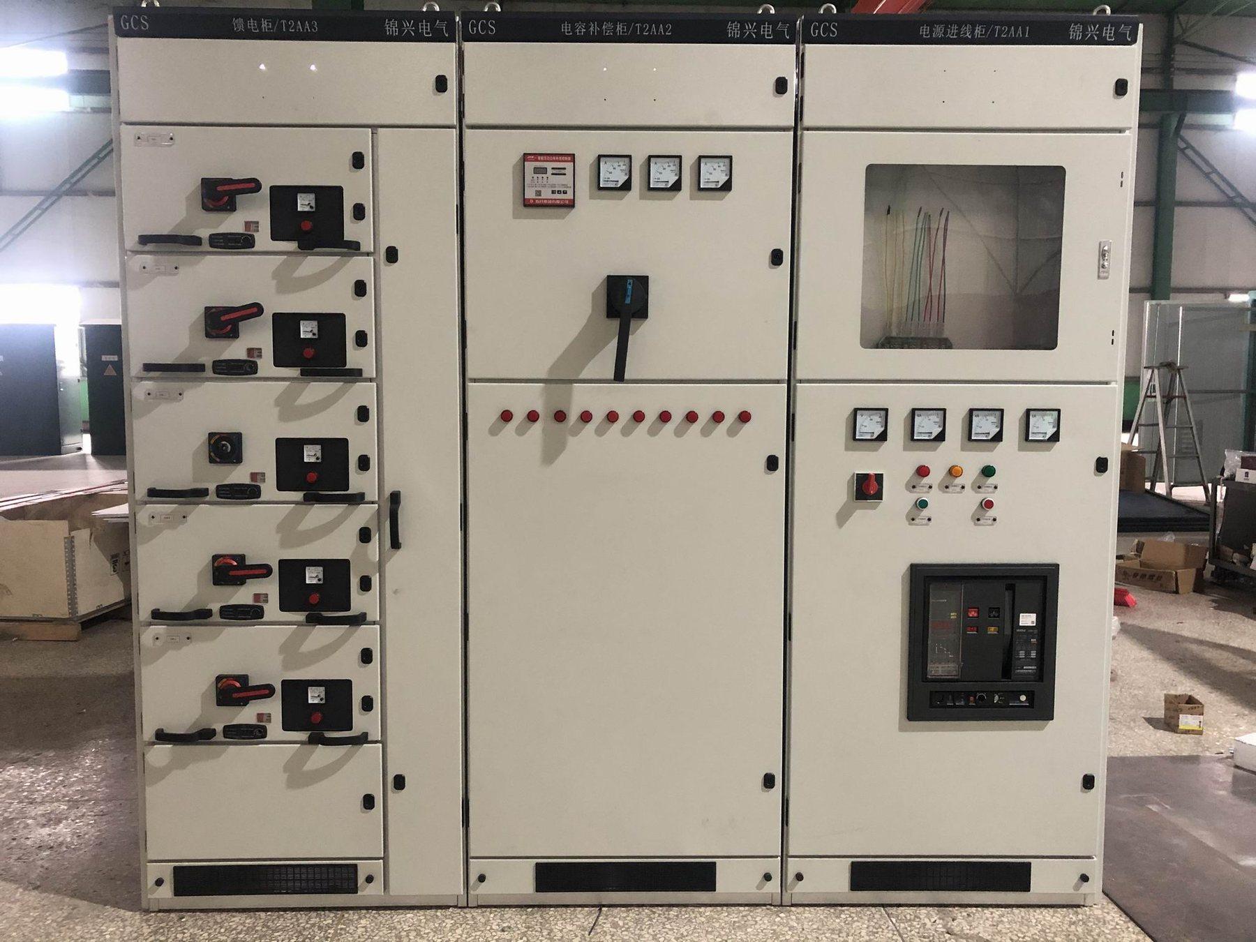
Describe the installed duty before comparing ampere ratings
The low-voltage switchgear range should be selected using a feeder schedule and the actual installation conditions. Two assemblies can display the same main-current value while differing in circuit arrangement, heat-producing devices, enclosure layout and the loading used for verification. Procurement needs those assumptions, not only a number on the front page.
Begin with the project ambient at the switchboard location and the operating load cases. Identify normal service, generator operation, temporary transfer states and foreseeable future circuits. The engineer should state which circuits may operate together. Treat a load-diversity assumption as an explicit project input; do not allow an undefined assumption to become an unnoticed reduction in the delivered duty.
Connect thermal evidence to the offered construction
| Review item | Information to put in the RFQ | Evidence to request |
|---|---|---|
| Ambient conditions | Temperature conditions at the actual assembly location | Declared installation limits and applicability statement |
| Feeder loading | Circuit currents and simultaneous operating cases | Accepted loading assumptions and thermal assessment basis |
| Enclosure | Dimensions, separation, doors and protection requirements | Offered construction tied to the verification evidence |
| Ventilation | Room conditions and allowed assembly openings | Ventilation arrangement and any stated dependencies |
| Devices and connections | Heat-producing equipment and incoming/outgoing interfaces | Device schedule, connection details and change controls |
| Evidence route | Contractual verification requirements and document scope | Applicable report, assessment or permitted comparison method |
| Final inspection | Manufactured arrangement and identified deviations | Routine records and approved as-built configuration |
The table does not prescribe a thermal limit or a verification method. Those must follow the agreed standard, contract and engineering assessment for the particular assembly.
Separate design applicability from routine checks
The design verification versus routine verification guide explains why documents answering different questions should not be exchanged. A routine delivery record confirms its stated checks on the manufactured assembly. It should not be relabelled as project-specific temperature-rise evidence when it does not establish that claim.
Request the evidence identity and the connection between the assessed design and the offered switchboard. If a reference design or comparison is proposed, ask the supplier to identify the relevant differences and the applicable assessment basis. The owner should know which statement is supported, what conditions it depends on and which deviations remain open. Do not describe a document for a component as proof for the complete assembly.
Review changes that alter heat or cooling
The LV switchgear IP and environment guide describes enclosure openings, seals and site conditions. A changed enclosure or ventilation arrangement may require the thermal applicability to be reviewed. Include that review in the variation process rather than accepting a higher protection code and assuming every other declaration remains unchanged.
Additional meters, communication devices, control supplies or future feeders can also change the configuration under review. The spare-feeder procurement guide helps distinguish an installed circuit from physical space. An empty compartment should not be treated as an already-verified loaded circuit when future equipment has not been defined.
Example: the room and enclosure change after award
An indoor assembly is initially offered for a ventilated room. The building design later relocates it to a warmer service area and requests a different enclosure arrangement. Procurement should request a revised applicability statement and any required changes before manufacturing release. Keeping the original main-current label without reviewing those altered conditions would leave the project's thermal question unanswered.
At final review, compare the approved drawings, device schedule and connection arrangement with the evidence package. Use the LV testing guide for the broader inspection plan and identify any additional site checks separately. Site observations do not automatically replace the agreed design-verification evidence.
RFQ checklist
- System voltage, frequency, main current, feeder schedule and quantity.
- Ambient conditions at the assembly and relevant room-cooling assumptions.
- Normal, alternative and future loading cases, including simultaneous loads.
- Required enclosure, separation, dimensions and ventilation restrictions.
- Device schedule and incoming/outgoing connection details.
- Applicable thermal verification requirement and document route.
- Reference-design differences, limitations and project approval responsibility.
- Changes that require renewed assessment before manufacturing release.
- Routine records, final drawings and site inspection responsibilities.
Send the loading and environment schedule through the LV switchgear product page or project enquiry page. Final current declarations and thermal evidence require confirmation for the offered assembly.